- 您现在的位置:买卖IC网 > Sheet目录887 > UCH-15/6.7-D48NB-C (Murata Power Solutions Inc)CONV DC/DC 100.5W 15V 6.7A
�� �
�
�Single� Output� UCH� Models�
�Isolated,� “Half-Brick”�
�1.8?15V� Output� DC/DC� Converters�
�Note� that� the� temperatures� are� of� the� ambient� air?ow,� not� the� converter�
�itself� which� is� obviously� running� at� higher� temperature� than� the� outside� air.�
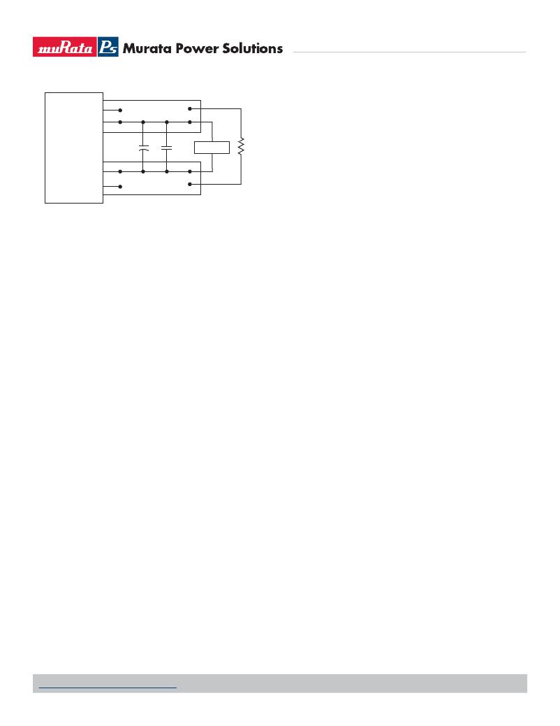
�+SENSE�
�+VOUT�
�Also� note� that� very� low� ?ow� rates� (below� about� 25� LFM)� are� similar� to� “natural�
�convection,”� that� is,� not� using� fan-forced� air?ow.�
�Murata� Power� Solutions� makes� Characterization� measurements� in� a� closed�
�C1�
�C2�
�SCOPE�
�R� LOAD�
�cycle� wind� tunnel� with� calibrated� air?ow.� We� use� both� thermocouples� and� an�
�infrared� camera� system� to� observe� thermal� performance.� As� a� practical� matter,�
�?VOUT�
�?SENSE�
�C1� =� 1μF�
�C2� =� 10μF�
�LOAD� 2-3� INCHES� (51-76mm)� FROM� MODULE�
�Figure� 3.� Measuring� Output� Ripple� and� Noise� (PARD)�
�Floating� Outputs�
�Since� these� are� isolated� DC/DC� converters,� their� outputs� are� “?oating”� with�
�respect� to� their� input.� The� essential� feature� of� such� isolation� is� ideal� ZERO�
�CURRENT� FLOW� between� input� and� output.� Real-world� converters� however� do�
�exhibit� tiny� leakage� currents� between� input� and� output� (see� Speci?cations).�
�These� leakages� consist� of� both� an� AC� stray� capacitance� coupling� component�
�and� a� DC� leakage� resistance.� When� using� the� isolation� feature,� do� not� allow�
�the� isolation� voltage� to� exceed� speci?cations.� Otherwise� the� converter� may�
�be� damaged.� Designers� will� normally� use� the� negative� output� (-Output)� as�
�the� ground� return� of� the� load� circuit.� You� can� however� use� the� positive� output�
�(+Output)� as� the� ground� return� to� effectively� reverse� the� output� polarity.�
�Minimum� Output� Loading� Requirements�
�All� models� regulate� within� speci?cation� and� are� stable� under� no� load� to� full�
�load� conditions.� Operation� under� no� load� might� however� slightly� increase�
�output� ripple� and� noise.�
�Thermal� Shutdown�
�To� prevent� many� over� temperature� problems� and� damage,� these� converters�
�include� thermal� shutdown� circuitry.� If� environmental� conditions� cause� the�
�temperature� of� the� DC/DC’s� to� rise� above� the� Operating� Temperature� Range�
�up� to� the� shutdown� temperature,� an� on-board� electronic� temperature� sensor�
�will� power� down� the� unit.� When� the� temperature� decreases� below� the� turn-on�
�threshold,� the� converter� will� automatically� restart.� There� is� a� small� amount� of�
�hysteresis� to� prevent� rapid� on/off� cycling.� The� temperature� sensor� is� typically�
�located� adjacent� to� the� switching� controller,� approximately� in� the� center� of� the�
�unit.� See� the� Performance� and� Functional� Speci?cations.�
�CAUTION:� If� you� operate� too� close� to� the� thermal� limits,� the� converter� may�
�shut� down� suddenly� without� warning.� Be� sure� to� thoroughly� test� your� applica-�
�tion� to� avoid� unplanned� thermal� shutdown.�
�Temperature� Derating� Curves�
�The� graphs� in� this� data� sheet� illustrate� typical� operation� under� a� variety� of�
�conditions.� The� Derating� curves� show� the� maximum� continuous� ambient� air�
�temperature� and� decreasing� maximum� output� current� which� is� acceptable�
�under� increasing� forced� air?ow� measured� in� Linear� Feet� per� Minute� (“LFM”).�
�Note� that� these� are� AVERAGE� measurements.� The� converter� will� accept� brief�
�increases� in� current� or� reduced� air?ow� as� long� as� the� average� is� not� exceeded.�
�it� is� quite� dif?cult� to� insert� an� anemometer� to� precisely� measure� air?ow� in�
�most� applications.� Sometimes� it� is� possible� to� estimate� the� effective� air?ow� if�
�you� thoroughly� understand� the� enclosure� geometry,� entry/exit� ori?ce� areas� and�
�the� fan� ?owrate� speci?cations.�
�CAUTION:� If� you� routinely� or� accidentally� exceed� these� Derating� guidelines,�
�the� converter� may� have� an� unplanned� Over� Temperature� shut� down.� Also,� these�
�graphs� are� all� collected� at� slightly� above� Sea� Level� altitude.� Be� sure� to� reduce�
�the� derating� for� higher� density� altitude.�
�Output� Overvoltage� Protection�
�This� converter� monitors� its� output� voltage� for� an� over-voltage� condition.� If�
�the� output� exceeds� OVP� limits,� the� sensing� circuit� will� power� down� the� unit,�
�and� the� output� voltage� will� decrease.� After� a� time-out� period,� the� PWM� will�
�automatically� attempt� to� restart,� causing� the� output� voltage� to� ramp� up� to� its�
�rated� value.� It� is� not� necessary� to� power� down� and� reset� the� converter� for� the�
�automatic� OVP-recovery� restart.�
�If� the� fault� condition� persists� and� the� output� voltage� climbs� to� excessive�
�levels,� the� OVP� circuitry� will� initiate� another� shutdown� cycle.� This� on/off� cycling�
�is� referred� to� as� “hiccup”� mode.� It� safely� tests� full� current� rated� output� voltage�
�without� damaging� the� converter.�
�Output� Fusing�
�The� converter� is� extensively� protected� against� current,� voltage� and� temperature�
�extremes.� However� your� output� application� circuit� may� need� additional� protec-�
�tion.� In� the� extremely� unlikely� event� of� output� circuit� failure,� excessive� voltage�
�could� be� applied� to� your� circuit.� Consider� using� an� appropriate� fuse� in� series�
�with� the� output.�
�Output� Current� Limiting�
�As� soon� as� the� output� current� increases� to� approximately� 125%� to� 150%� of�
�its� maximum� rated� value,� the� DC/DC� converter� will� enter� a� current-limiting�
�mode.� The� output� voltage� will� decrease� proportionally� with� increases� in� output�
�current,� thereby� maintaining� a� somewhat� constant� power� output.� This� is� also�
�commonly� referred� to� as� power� limiting.�
�Current� limiting� inception� is� de?ned� as� the� point� at� which� full� power� falls�
�below� the� rated� tolerance.� See� the� Performance/Functional� Speci?cations.�
�Note� particularly� that� the� output� current� may� brie?y� rise� above� its� rated� value�
�in� normal� operation� as� long� as� the� average� output� power� is� not� exceeded.� This�
�enhances� reliability� and� continued� operation� of� your� application.� If� the� output�
�current� is� too� high,� the� converter� will� enter� the� short� circuit� condition.�
�Output� Short� Circuit� Condition�
�When� a� converter� is� in� current-limit� mode,� the� output� voltage� will� drop� as� the�
�output� current� demand� increases.� If� the� output� voltage� drops� too� low� (ap-�
�proximately� 98%� of� nominal� output� voltage� for� most� models),� the� magnetically�
�www.murata-ps.com/support�
�MDC_UCH� Models.C01� Page� 15� of� 18�
�发布紧急采购,3分钟左右您将得到回复。
相关PDF资料
UCJ1V101MCL1GS
CAP ALUM 100UF 35V 20% SMD
UCL1V151MNL1GS
CAP ALUM 150UF 35V 20% SMD
UCS2E330MHD1TO
CAP ALUM 33UF 250V 20% RADIAL
UCW1V331MNL1GS
CAP ALUM 330UF 35V 20% SMD
UCY2V120MPD
CAP ALUM 12UF 350V 20% RADIAL
UCZ1E331MCL1GS
CAP ALUM 330UF 25V 20% SMD
UDB1H150MHM
CAP ALUM 15UF 50V 20% RADIAL
UEE-3.3/30-D48PB-C
36-75VIN 3.3VOUT 99W POS LOGIC
相关代理商/技术参数
UCH-15/6.7-D48NB-C
制造商:Murata Power Solutions 功能描述:DC/DC Converter
UCH-15/6.7-D48N-C
功能描述:DC/DC转换器 15Vout 6.7A 100.5W 48Vin Neg Polarity
RoHS:否 制造商:Murata 产品: 输出功率: 输入电压范围:3.6 V to 5.5 V 输入电压(标称): 输出端数量:1 输出电压(通道 1):3.3 V 输出电流(通道 1):600 mA 输出电压(通道 2): 输出电流(通道 2): 安装风格:SMD/SMT 封装 / 箱体尺寸:
UCH-15/6.7-D48PB-C
功能描述:DC/DC转换器 48V 15Vot 6.7A100.5W pos polrty w/Baseplt RoHS:否 制造商:Murata 产品: 输出功率: 输入电压范围:3.6 V to 5.5 V 输入电压(标称): 输出端数量:1 输出电压(通道 1):3.3 V 输出电流(通道 1):600 mA 输出电压(通道 2): 输出电流(通道 2): 安装风格:SMD/SMT 封装 / 箱体尺寸:
UCH-15/6.7-D48P-C
功能描述:DC/DC转换器 48V 15Vot 6.7A100.5W positive polarity RoHS:否 制造商:Murata 产品: 输出功率: 输入电压范围:3.6 V to 5.5 V 输入电压(标称): 输出端数量:1 输出电压(通道 1):3.3 V 输出电流(通道 1):600 mA 输出电压(通道 2): 输出电流(通道 2): 安装风格:SMD/SMT 封装 / 箱体尺寸:
UCH1V101MCL1GS
功能描述:100μF 35V Aluminum Capacitors Radial, Can - SMD 300 mOhm @ 100kHz 2000 Hrs @ 125°C 制造商:nichicon 系列:UCH 包装:剪切带(CT) 零件状态:有效 电容:100μF 容差:±20% 额定电压:35V ESR(等效串联电阻):300 毫欧 @ 100kHz 不同温度时的使用寿命:125°C 时为 2000 小时 工作温度:-40°C ~ 125°C 极化:极化 应用:通用 纹波电流:98.5mA @ 120Hz 阻抗:- 引线间距:- 大小/尺寸:0.248" 直径(6.30mm) 高度 - 安装(最大值):0.315"(8.00mm) 表面贴装焊盘尺寸:0.260" 长 x 0.260" 宽(6.60mm x 6.60mm) 安装类型:表面贴装 封装/外壳:径向,Can - SMD 标准包装:1
UCH1V221MCL1GS
功能描述:CAP ALUM 220UF 20% 35V SMD 制造商:nichicon 系列:UCH 包装:剪切带(CT) 零件状态:在售 电容:220μF 容差:±20% 电压 - 额定:35V ESR(等效串联电阻):200 毫欧 @ 100kHz 不同温度时的使用寿命:125°C 时为 2000 小时 工作温度:-40°C ~ 125°C 极化:极化 等级:- 应用:通用 Ripple Current:135mA @ 120Hz Ripple Current @ High Frequency:270mA @ 100kHz 引线间距:- 大小/尺寸:0.315" 直径(8.00mm) 高度 - 安装(最大值):0.425"(10.80mm) 表面贴装焊盘尺寸:0.327" 长 x 0.327" 宽(8.30mm x 8.30mm) 安装类型:表面贴装 封装/外壳:径向,Can - SMD 标准包装:1
UCH1V331MCL1GS
功能描述:35V 330UF 20% HIGH RELIABILITY-S 制造商:nichicon 系列:UCH 包装:剪切带(CT) 零件状态:在售 电容:330μF 容差:±20% 电压 - 额定:35V ESR(等效串联电阻):150 毫欧 @ 100kHz 不同温度时的使用寿命:125°C 时为 2000 小时 工作温度:-40°C ~ 125°C 极化:极化 等级:- 应用:通用 Ripple Current:250mA @ 120Hz Ripple Current @ High Frequency:500mA @ 100kHz 引线间距:- 大小/尺寸:0.394" 直径(10.00mm) 高度 - 安装(最大值):0.425"(10.80mm) 表面贴装焊盘尺寸:0.406" 长 x 0.406" 宽(10.30mm x 10.30mm) 安装类型:表面贴装 封装/外壳:径向,Can - SMD 标准包装:1
UCH1V470MCL1GS
功能描述:47μF 35V Aluminum Capacitors Radial, Can - SMD 300 mOhm @ 100kHz 2000 Hrs @ 125°C 制造商:nichicon 系列:UCH 包装:剪切带(CT) 零件状态:有效 电容:47μF 容差:±20% 额定电压:35V ESR(等效串联电阻):300 毫欧 @ 100kHz 不同温度时的使用寿命:125°C 时为 2000 小时 工作温度:-40°C ~ 125°C 极化:极化 应用:通用 纹波电流:98.5mA @ 120Hz 阻抗:- 引线间距:- 大小/尺寸:0.248" 直径(6.30mm) 高度 - 安装(最大值):0.315"(8.00mm) 表面贴装焊盘尺寸:0.260" 长 x 0.260" 宽(6.60mm x 6.60mm) 安装类型:表面贴装 封装/外壳:径向,Can - SMD 标准包装:1